Engineering Drawing Standards Explained:
Revisions Waste Time & Money! How many times has your momentum on a project been slowed down by having to revise drawings sent to would-be vendors?
Your time is valuable, and delays can be costly. We’ve put together an eBook to help professionals like you make sure that your drawings have everything a partner or vendor could need.
Engineering drawings are the medium through which engineers communicate the design requirements of an engineered product or component. Often termed as mechanical drawings, manufacturing blueprints, or dimensional prints, engineering drawings accurately and clearly capture all the geometric features of the components or products illustrated in the drawing. A clear and technically accurate drawing will ultimately allow the manufacturer or fabricator to produce the component without any errors.
 Apart from describing the shape and size of an object, engineering drawings sometimes also include information such as acceptable variations, materials, load limits, and other design parameters to give a clear picture of the component or product manufactured.
Every manufacturing drawing follows a specific standard so that they are easy to interpret. Standardized drawings also ensure clear communication between teams, reduced manufacturing errors, and faster production. This brief guide explains the essential elements of engineering drawings and the ways through which you can create these technical documents or manufacturing blueprints.
How Do You Make Engineering Drawings?
Before the introduction of computer aided drafting, drafting engineering drawings was a manual process. Depending on the complexity of the design, these drawings required several days of hard work and skilled drafters working together with drawing boards, pencils, and other measuring instruments. Some of the tools used in this manual drawing process are drawing sheet, board, drafter, compass, T-square, divider, climograph, set squares, protractor, templates, and French curves.
However, today, several CAD tools are available that make creating an engineering drawing quick and efficient. Some popular CAD tools available today include AutoCAD, DraftSight, SolidWorks, TinkerCAD, and Creo.
Different Elements of Engineering Drawings
Effective engineering drawings must fulfill the following two requirements:
- Convey information to create a component without the need for asking any questions
- Must not have any ambiguity, which can lead to the making of a too expensive component.
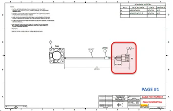
Every engineering drawing comprises different essential elements that help to share its technical details with the viewers. For example, in the case of cable manufacturing, the engineering drawing typically includes the following elements:
- Revision Block: It is a table that shows the number of times the drawings have been revised.
- Notes: It is a section that typically includes symbols breakdown, dimensional standards, industry standards, and any other references to specific items illustrated in the drawing.
- Title Block: This section typically contains the drawing title, part number, and description.
- Grid: Grid breaks the entire drawing document into sections that engineers can use to call out specific sections of the drawing that needs attention.
- Connector Illustrations: This element provides all the details about the connector used in the cable.
- UOM & Tolerance: It is a section where measurement units and tolerance details are mentioned.
- Length Designations: This element shows where the item is intended to be measured from.
- Wire Run List: This section highlights the wire position for each connector.
- Markers & Label Section: This section is a table that provides the details about the marker/label length used on the cable.
- Bill of Materials (BOM): It is a table that lists all the components used in the cable drawing. BOM is an essential element that ensures correct components are purchased for cable manufacturing.
An engineering drawing with all these elements listed accurately will help to eliminate the time taken for unnecessary explanations, communication issues and help manufacture cables without any errors.